
Network
World Clear Choice Test: Enterprise Wi-Fi Scalability
Published in Network
World, 6 November 2006
Test Methodology
Version 2006110601. Copyright
2006 by Network Test Inc. Vendors may comment on this document and any other
aspect of test methodology. Network Test and Opus One reserve the right to
change test parameters at any time.
1 Executive summary
This document describes benchmarking procedures for enterprise wireless LAN systems. Test results appear in the November 6, 2006 edition of Network World.
These tests assess WLAN performance and scalability using the following metrics:
- Throughput
- Latency
- Call capacity with one AP
- Call capacity with 25 APs
- Roaming with one client
- Roaming with many clients
This document is organized as follows. This section
introduces the tests to be conducted. Section 2 describes the test bed. Section
3 describes the tests to be performed. Section 4 provides a change log.
2 The test bed
2.1 System under test
The system under test must include the following components:
- At least 27 access points (APs). We plan to test with 25 APs from each vendor, with two held aside as spares. Access points must support 802.11b/g and should support 802.3af power over Ethernet. (Also see comments in the next section about SMA connectors.)
- If
supported, at least two switches or controllers to manage the APs.
Switches should offer enough PoE-capable copper Ethernet interfaces to
connect all APs, plus at least one 10/100/1000 connection on each device
to the network backbone. Note the gigabit copper uplink; please contact us
ASAP if your device supports only fiber 1000SX uplinks. Switches also must support IEEE 802.1q VLAN tagging.
Example: A vendor may supply two switches: one with 24 10/100 PoE ports plus two copper gigabit ports, and the other with 8 10/100 PoE ports plus one copper gigabit port. - If desired, some means of routing traffic between IP subnets. If the system under test does not support IP routing, we will supply L3 functionality using devices previously tested to show line-rate performance and low latency (on the order of dozens of microseconds).
The following diagram shows the test bed. At left are VeriWave WT-90 test instruments, described below.
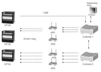
We place each of the 25 APs in its own RF-shielded enclosure to reduce interference. If the AP has a detachable antenna and an SMA connector, then we will run a cable between the AP and the rear of the enclosure. If the AP has only internal or non-detachable antenna(s), we will place the 802.11a/b/g antenna within the RF shielded enclosure, which in turn attaches via cable to the WT-90 test instrument. If the AP has a detachable antenna, but does not use an SMA connector, vendors are strongly encouraged to supply an adapter.
We may insert RF attenuators between the WT-90 and the APs to create an RSSI level of -30 to -40 dBm.
The APs should support both 802.11b and 802.11g. For throughput and latency measurement, the wireless clients will use 802.11g at 54Mbps for the best possible performance. APs should use 802.3ae power over Ethernet. Again, let us know ASAP if your device does not support PoE.
The WLAN system and each AP will advertise and support three networks: a corporate data network (SSID=NetTestData), a VoIP network (SSID=NetTestVoice), and a guest network (SSID=NetTestGuest).
The NetTestData network will require client connections with WPA2 (AES/CCMP) encryption and PEAP/MS-CHAPv2 authentication. Each AP will have 20 802.11b/g clients connected to this network for the throughput, latency, and roaming tests.
The NetTestVoice network will require clients with WPA/PSK security, using a preshared key of “NetTestVoice”. We will use this network to perform the call capacity test. If supported, vendors should enable QoS mechanisms should to prioritize traffic from the NetTestVoice network.
The NetTestGuest network will have open security and will be used to introduce background traffic.
The Ethernet link connected to the network backbone will have 1 to 20 servers (depending upon the test) connected to it. This makes a total of 500 wireless clients and 20 Ethernet clients.
We assume all systems under test will comprise at least two WLAN controllers plus access points. One WLAN controller MUST have the lesser of either 20 or the maximum number of APs connected to it, and the second controller the remaining APs. By using two controllers as a system under test, we plan to demonstrate how the system will perform as networks grow.
We are glad to test products that do not include a wired Ethernet controller; however, vendors MUST submit their own switches/power injectors as part of the system under test, and include their cost in the price as tested.
2.2 System under test configuration
The test will use a mix of static and dynamic IPv4 addresses across 7 VLANs. VLAN100 is reserved for the SUT management. The subnet mask is 255.255.255.0 for all VLANs. The address of 10.0.x.254 is reserved for gateways.
|
Name |
Devices |
SSID |
IP addresses |
Static/
dynamic |
VLAN |
|
SUT management |
SUT |
|
10.0.0.0/24 |
Static |
100 |
|
Workgroup A |
AP01 – AP05 |
NetTestData |
10.0.1.0/24 |
dynamic |
101 |
|
Workgroup B |
AP06 – AP10 |
NetTestData |
10.0.2.0/24 |
dynamic |
102 |
|
Workgroup C |
AP11 – AP15 |
NetTestData |
10.0.3.0/24 |
dynamic |
103 |
|
Workgroup D |
AP16 – AP20 |
NetTestData |
10.0.4.0/24 |
dynamic |
104 |
|
Workgroup E |
AP21 – AP25 |
NetTestData |
10.0.5.0/24 |
dynamic |
105 |
|
Phone group A |
AP01 – AP05 |
NetTestVoice |
10.0.101.0/24 |
dynamic |
201 |
|
Phone group B |
AP06 – AP10 |
NetTestVoice |
10.0.102.0/24 |
dynamic |
202 |
|
Phone group C |
AP11 – AP15 |
NetTestVoice |
10.0.103.0/24 |
dynamic |
203 |
|
Phone group D |
AP16 – AP20 |
NetTestVoice |
10.0.104.0/24 |
dynamic |
204 |
|
Phone group E |
AP21 – AP25 |
NetTestVoice |
10.0.105.0/24 |
dynamic |
205 |
|
Guest group A |
AP01 – AP05 |
NetTestGuest |
10.0.201.0/24 |
dynamic |
301 |
|
Guest group B |
AP06 – AP10 |
NetTestGuest |
10.0.202.0/24 |
dynamic |
302 |
|
Guest group C |
AP11 – AP15 |
NetTestGuest |
10.0.203.0/24 |
dynamic |
303 |
|
Guest group D |
AP16 – AP20 |
NetTestGuest |
10.0.204.0/24 |
dynamic |
304 |
|
Guest group E |
AP21 – AP25 |
NetTestGuest |
10.0.205.0/24 |
dynamic |
305 |
|
Auth server |
Windows Server |
|
10.0.10.22/24 |
static |
106 |
|
Network backbone |
ETH0 |
|
10.0.11.1 –
10.0.11.20/24 |
static |
107 |
Every AP, Ethernet controller, and any Management console should be statically configured on the 10.0.0.0/24 network; please contact us ASAP for your address allocation. Segregating management traffic on its own subnet and VLANs ensures that this traffic will not affect measurements on other VLANs.
There will be 5 different VLANs supporting the 500 wireless clients. Each of these VLANs will span 5 different APs. The 500 wireless clients will use DHCP to obtain IP addresses.
As described above, the SSID for all APs MUST be set to “NetTestData”, “NetTestVoice”, and “NetTestGuest”.
The last VLAN will contain the 20 clients acting as a network backbone and the Windows Server 2003 Enterprise Edition authentication server running IAS. Controllers and/or access points should use a shared secret of “NetTest” to communicate with the IAS RADIUS server.
The wired Ethernet controllers MUST be able to forward DHCP traffic.
The Username/password for the wireless clients will follow the pattern “UserAAUU” and “PassAAUU”, where “AA” is the AP number and UU is the user number. For example, AP 1, user 1 has a username “User0101” and password of “Pass0101” while AP 17, user 12 has a username User1712” and password of “Pass1712”.
L2 MAC addresses of the clients will follow the IETF draft draft-ietf-bmwg-hash-stuffing-05.txt. For more information, see http://www.ietf.org/internet-drafts/draft-ietf-bmwg-hash-stuffing-05.txt
2.3 Test instrument
VeriWave’s WT-90 is a Wireless LAN and Ethernet performance test platform, capable of stress testing a complete WLAN network, including Access Points (APs) and WLAN switches. The WT-90 provides simultaneous generation of traffic from thousands of 802.11 and Ethernet clients, with line-rate analysis of the behavior of the system being tested. In addition to complex generation and analysis capabilities, the WT-90 system also offers full capture and decode of all WLAN traffic. For more information, visit http://www.VeriWave.com/products/wavetest.asp
3 Test Procedures
3.1 Throughput
3.1.1 Objective
To determine the SUT throughput (as defined in RFC 1242) for a single AP and 20 clients
To determine the SUT throughput (as defined in RFC 1242) for maximum number of APs, each with 20 clients
3.1.2 Test bed configuration
Topology is partially meshed, multiple device (as defined in RFC 2889, aka “backbone”) with all traffic offered from wired Ethernet to wireless LAN clients
|
Test duration |
60 seconds |
|
Test traffic frame sizes |
88, 512, and 1,518 bytes (as offered on 802.3 side) |
|
Traffic orientation |
Unidirectional Ethernet to Wireless |
|
Acceptable Loss |
0.1% |
|
Search Resolution |
1.0% |
|
Client Contention |
Zero |
Run throughput test in two configurations:
Single AP with 20 clients and a single Ethernet client
max APs, 20 clients per AP and 20 Ethernet clients
Run throughput test in two configurations:
- Single AP with 20 clients and a single Ethernet client
- Maximum APs, 20 clients per AP and 20 Ethernet clients
This test will be run using the corporate data network (SSID= NetTestData). No traffic or connections will be present on the other networks.
3.1.3 Procedures
Using VeriWave’s Standard WLAN Benchmarking Test to measure throughput (per RFC1242), Network Test will determine the maximum forwarding rate each system under test can sustain with zero packet loss.
The Standard WLAN Benchmarking Test determines the throughput using a binary search algorithm. The binary search algorithm uses two parameters in its search: the maximum passed rate and the maximum failed rate. On the first test iteration, a configured maximum rate is attempted (default is 150% of computed theoretical maximum). If the amount of packet loss is acceptable, then the search is terminated and the configured rate is reported. If the measured packet loss exceeds the Acceptable Loss, then the binary search algorithm will attempt another test iteration half way between the maximum passed rate and the maximum failed rate. The binary search algorithm continues this process until difference between Offered Load values is less than the Search Resolution setting. At each iteration the binary search algorithm updates the maximum passed rate and the maximum failed rate before computing the next value to attempt.
Between the iterations, the WT-90 will measure the RSSI value of the AP’s beacons. At the end of the test, the report will contain the minimum, maximum, and average RSSI per access point. If the RSSI values are not in the range of -60 dBm to -20 dBm, the number of retransmission may be higher than expected and the reported throughput lower.
3.1.4 Metrics
Throughput in frames per second and bits per second
3.2 Latency
3.2.1 Objective
To determine the SUT latency and jitter for a single AP and 20 clients, both at the throughput rate and at 10 percent utilization.
To determine the SUT latency and jitter for maximum number of APs, each with 20 clients, both at the throughput rate and at 10 percent utilization.
3.2.2 Test bed configuration
Topology is partially meshed, multiple device (as defined in RFC 2889, aka “backbone”) with all traffic offered from wired Ethernet to wireless LAN clients
|
Test duration |
60 seconds |
|
Intended Load |
Throughput and 10% of theoretical maximum |
|
Test traffic frame sizes |
88, 512, and 1,518 bytes (as offered on 802.3 side) |
|
Traffic orientation |
Unidirectional Ethernet to Wireless |
|
Client Contention |
Zero |
Run latency test in two configurations:
- Single AP with 20 clients and a single Ethernet client
- Maximum APs, 20 clients per AP and 20 Ethernet clients
This test will be run using the corporate data network (SSID= NetTestData). No traffic or connections will be present on the other networks.
3.2.3 Procedures
Using VeriWave’s Standard WLAN Benchmarking Test, Network Test will measure the minimum latency, maximum latency, average latency and jitter. Latency is the time between the first data bit of the frame leaving the Ethernet port and the first data bit of the frame entering the wireless port (as seen on the WT-90). Jitter is the standard deviation of the latencies for every data frame.
The test will consist of 12 iterations: all combinations of the 2 configurations, the 2 Intended loads and the 3 frame sizes. For each iteration, the VeriWave WT-90 will offer test frames on the Ethernet port at the configured load. For each of the VeriWave frames reaching the wireless port, the WT-90 computes latency. A VeriWave frame is unique in two ways: 1. it has a unique pattern identifiable by the WT-90 and 2. It has the string “VeriWave” after the UDP/IP header (making it easy to see in packet captures).
Between iterations, the WT-90 will measure the RSSI value of the AP’s beacon frames. At the end of the test, the report will contain the minimum, maximum, and average RSSI per access point. If the RSSI values are not in the range of -60 dBm to -20 dBm, the number of retransmissions may be higher than expected and increase the latency. (As noted, we use attenuators to ensure no AP runs at a signal strength greater than -20 dBm.)
3.2.4 Metrics
Jitter and minimum, average, maximum latency at throughput rate
Jitter and minimum, average, maximum latency at 10 percent of throughput rate
3.3 Call capacity
3.3.1 Objective
To determine the maximum number of concurrent VoIP calls a single AP can support with a defined level of quality while in the presence of sustained background data.
To determine the maximum number of concurrent VoIP calls the system under test can support with a defined level of quality while in the presence of sustained background data.
3.3.2 Test bed configuration
This test uses up to 24 APs. Topology is 20 802.11b clients per AP with a single Ethernet client. The WT-90 test instrument emulates 802.11b VoIP handsets and 802.11g data clients. Voice flows are a bidirectional pair between two clients on the same AP, or spread across different APs in the multiple-AP test.
|
Test duration |
300 seconds |
|
Sample Time |
30 seconds |
|
Client Call Delay |
250 milliseconds |
|
Calls on the same AP |
50% |
|
Maximum Call Packet Loss |
5% |
|
Minimum Call OLOAD |
95% |
|
Average latency |
< 100ms |
|
Search resolution |
Single-AP test: 1 call; 24-AP test: 12 calls |
|
Client contention |
Zero |
This test will be performed using the Voice network (SSID=NetTestVoice) and guest network (SSID=NetTestGuest).
Note: It takes approximately 45 to 60 minutes to determine the maximum number of concurrent VoIP calls. The number of iterations for this event will be limited. Please prepare to have the best results the first test run.
3.3.3 Procedures
Using VeriWave’s Standard WLAN Benchmarking Test to measure call capacity, Network Test will determine maximum call loading capacity of a SUT when VoIP calls are placed while the handsets maintain connection with the call server.
The test is first run with a single AP with 20 clients and then repeated with 24 APs, each with 20 clients.
Single-AP test: Each of 20 clients will connect as an 802.11b client running at 11Mbps. The WT-90 creates a total of 10 call sessions. A call session is defined as 2 clients, a bidirectional voice flow between the two clients with a 236-byte frame every 20 milliseconds (emulating RTP traffic and G.711 encoding, which typically uses 200-byte IP packets). The Ethernet client will offer background data traffic at15 Mbit/s on the guest network as downlink traffic.
At certain times during the test duration (defined by the sample time), the test instrument measures call quality. If call packet loss is less than the configured maximum, and the offered load is at least 95 percent of the intended load, then the call is not dropped. Each call is checked for quality at different times (staggered by the client call delay). If a single call is dropped, then the iteration is failed and will terminate immediately.
A binary search algorithm is used to determine the number of active sessions on a particular iteration. The binary search algorithm uses two parameters in its search: the maximum passed calls and the maximum failed calls. On the first test iteration, a configured maximum calls is attempted (10 call sessions). If the iteration does not drop any calls, then the search is terminated and the configured number is reported. If a call is dropped for the reason listed above, then the binary search algorithm will attempt another test iteration half way between the maximum passed and the maximum failed. The binary search algorithm continues this process until difference between the values is less than the Search Resolution setting. At each iteration, the binary search algorithm updates the maximum passed calls and the maximum failed calls before computing the next value to attempt.
24-AP test: The test instrument sets set up 20 voice clients on each AP, for a total of 480 voice clients. Each client will connect as an 802.11b client running at 11Mbps. The WT-90 creates a total of 240 call sessions. A call session is defined as 2 clients, a bidirectional voice flow between the two clients with a 236-byte frame every 20 milliseconds (emulating RTP traffic and G.711 encoding, which typically uses 200-byte IP packets). The Ethernet client will offer background data traffic at15 Mbit/s on the guest network as downlink traffic.
At certain times during the test duration (defined by the sample time), the test instrument measures call quality. If call packet loss is less than the configured maximum, and the offered load is at least 95 percent of the intended load, then the call is not dropped. Each call is checked for quality at different times (staggered by the client call delay). If a single call is dropped, then the iteration is failed and will terminate immediately.
A binary search algorithm is use to determine the number of active sessions on a particular iteration. The binary search algorithm uses two parameters in its search: the maximum passed calls and the maximum failed calls. On the first test iteration, a configured maximum calls is attempted (240 call sessions). If the iteration does not drop any calls, then the search is terminated and the configured number is reported. If a call is dropped for any of the reasons listed above, then the binary search algorithm will attempt another test iteration halfway between the maximum passed and the maximum failed. The binary search algorithm continues this process until difference between the values is less than the search resolution setting. After each iteration the binary search algorithm updates the maximum passed calls and the maximum failed calls before computing the next value to attempt.
Note that the binary search algorithm may produce some iterations where the test instrument attempts an odd number of calls. In such cases, the test instrument will distribute calls starting from the lowest-number AP. For example, in an iteration with 301 attempted calls, the test instrument will place 13 calls through the first 13 APs (169 calls), and 12 calls through the last 11 APs (132 calls, for a total of 301).
3.3.4 Metrics
VeriWave’s Standard WLAN Benchmarking Test reports the number of calls placed, number of calls succeeded, number of calls failed, min/max/avg latency and jitter.
3.4 Roaming with one client
3.4.1 Objective
To determine roaming time for one client migrating from one access point to another.
3.4.2 Test bed configuration
We use all 25 APs in this test. A single client will configured and associated with the APs.
|
Dwell Time |
250 seconds |
This test will be run using the corporate data network (SSID=NetTestData). No traffic or connections will be present on the other networks.
3.4.3 Procedures
VeriWave’s Standard WLAN Benchmarking Test will be used to measure roaming delay. Before the Test duration, a client will associate with the access point closest to the Windows Server 2003 Enterprise Edition authentication server.
At the beginning of the test duration, the Ethernet client will send 128-byte frames at 1000 frames per second. These frames simulate streaming media. We measure the roaming delay. The frame rate is higher than voice media in order to keep the measurement error to +/- 1 millisecond.
At 250-second intervals after the test has started, the client will initiate a roam event by associating to another AP. If the roam event was successful, we record the roaming delay. Roaming delay is measured starting from the point where the client makes the roaming decision (i.e., moves away from the current AP) to when the first data packet is received from the new AP.
The client will roam to all 25 APs over the duration of this test. Roaming times for a single client form the basis of comparison with the test in the next section, where many clients roam simultaneously.
At the end of the test duration, the minimum, maximum, and average roaming delay for the 20 roam events are recorded. Failed roam events are also counted.
3.4.4 Metrics
Minimum roaming times (milliseconds)
Average roaming time (milliseconds)
Maximum roaming time (milliseconds)
Failed roams
Note: “Roaming time” refers to the roaming interval attributable to the AP and/or controller/switch, not the client. The VeriWave test instrument measures roaming time for both client and AP/controller/switch contributions to roaming time, and we report only the time attributable to the system under test.
3.5 Roaming with many clients (aka “merry-go-round of death”)
3.5.1 Objective
To measure the SUT’s ability to handle a company with large numbers of mobile users. Using 500 clients associated evenly across 25 APs, some 250 of the clients will move to a new AP once per second, with a total of 12,500 roam events.
3.5.2 Test bed configuration
A total of 25 APs will be involved in the test. Each AP will have 20 clients associated to it, for a total of 500 clients, only 250 of which will roam. Every 1 second, a single client will roam to the AP on its right. At no time will there be more than 40 clients associated to a single AP. This process continues until clients end back at their starting place – just like a giant merry-go-round. The entire cycle is repeated twice, so there are a total of 12,500 roam events (250 clients * 25 APs * 2 complete cycles).
|
Test duration |
6250 seconds (~ 104 minutes) |
|
Total Clients |
500 |
|
Roaming Clients |
250 |
|
Client Distribution |
Clients distributed among APs |
|
Dwell Time |
250 seconds |
|
Time Distribution |
Even Time Distribution |
This test will be run using the corporate data network (SSID= NetTestData). No traffic or connections will be present on the other networks.
Note: VeriWave’s Jerry Perser coined the term “merry-go-round of death” for this test. Perser could not use the term “Carousel of Progress” due to Disney’s copyright, so he instead imagined a large crowd of screaming, Wi-Fi-enabled executives walking in circles.
3.5.3 Procedures
VeriWave’s Standard WLAN Benchmarking Test will be used to measure roaming delay. Before the Test duration, 500 clients will associate with the APs (20 per AP).
At the beginning of the test duration, the Ethernet client will send 128 byte frames at 100,000 frames per second (or 12% OLOAD). This works out to100 frames/sec per wireless client. These frames are used to simulate streaming media and measure the roaming delay. The frame rate is higher than voice media in order to keep the measurement error to +/- 5 millisecond.
At 500 millisecond intervals after the test has started, one client will initiate a roam event by associating to the next AP on the list. For example, if the client was on AP12 then he would roam to AP13. Clients on AP25 will roam to AP01. If the roam event was successful, the Roaming delay is recorded. Roaming delay is measured starting from the point where the client makes the roaming decision (i.e., moves away from the current AP) to when the first data packet is received from the new AP.
At the end of this 104-minute fright ride, the minimum, maximum, and average roaming delay for the 12,500 roam events are recorded. Failed roam events (the death part) are also counted.
3.5.4 Metrics
Minimum roaming time (milliseconds)
Average roaming time (milliseconds)
Maximum roaming time (milliseconds)
Failed roams
Average forwarding rate per client (roaming group)
Average forwarding rate per client (non-roaming group)
Note: “Roaming time” refers to the roaming interval attributable to the AP and/or controller/switch, not the client. The VeriWave test instrument measures roaming time for both client and AP/controller/switch contributions to roaming time, and we report only the time attributable to the system under test.
4 Change Log
Version 2006110601
Changed title to indicate publication in Network World
Version 2006083101
Section 2.2
Fixed VLAN ID for network backbone (was 106, now 107)
Section 3.1.2
Changed acceptable loss from 0.0% to 0.1% to accommodate design flaw in 802.11 protocol
Version 2006082301
Section 3.3.2: Removed references to polling and heartbeats; only VoIP traffic is now between handsets
Sections 3.5.1, 3.5.2:
Version 2006080901
Section 2.2: Corrected IP addressing in table; Ethernet clients now in 10.0.11.0/24 subnet
Section 3.1.2: Use a 1.0% resolution (was 0.1%) to reduce the number of iterations
Section 3.3.1: Added single-AP objective
Section 3.3.2: Specified that voice clients use 802.11.b and data clients use 802.11g. Changed client call delay to 250 ms (was 1 second)
Section 3.3.4: Added metric of aggregate forwarding rate for data clients
Sections 3.4.4 and 3.5.4: Added note clarifying that roaming time measures SUT and not client contribution to roaming interval
Version 2006071201
Section 2.2: Corrected IP addressing in table; added details on RADIUS authentication
Version 2006062901
Sections 2 and 3: Added multiple SSIDs for multiple traffic classes
Section 3.4: Client now roams across all APs, not just two APs; dwell time increased from 6 to 250 seconds
Section 3.5: Dwell time increased from 120 to 250 seconds
Version 2006062601
Initial public release