
Network
World Clear Choice Test: Access Switches
Scheduled
for publication in Network World in March 2008
Test Methodology
Version
2008012101. Copyright 1999-2008 by Network Test Inc. Vendors are encouraged to
comment on this document and any other aspect of test methodology. Network Test
and Network World reserve the right to change test parameters at any time.
PDF version: http://networktest.com/10g07/10g07meth.pdf
1
Executive summary
This document describes
benchmarking procedures for gigabit/10 gigabit access switches. Test results
are scheduled for publication in Network World in March 2008.
Given that Network World’s
readership is comprised of enterprise network managers, the key emphases of
this project will be performance, security, and features in an enterprise
context. As described in detail below, tests cover the following areas:
- L2
unicast performance
- L3 unicast performance
- IGMP
multicast group capacity
- L2
multicast performance
- L3 multicast performance
- NAC/802.1X
support
- Storm
control
- Power
consumption
- Switch
management and usability
- Switch
features (VLANs, routing, discovery, etc.)
This document is organized as follows. This section
introduces the tests to be conducted. Section 2 describes the test bed. Section
3 describes the tests to be performed. Section 4 provides a change log.
2
The test bed
This section discusses requirements of systems under test
and introduces the test equipment to be used.
2.1
Devices under test
Participating vendors should supply the following:
- One
access switch equipped with at least two 10-gigabit Ethernet uplinks and
at least 48 10/100/1000 access ports.
- At
least two optical transceivers for the 10-gigabit ports. We assume the use
of 10GBASE-SR XFP transceivers but may be able to accommodate other
transceiver types such as XENPAK or X2. Please let us ASAP if your system
uses some other transceiver type.
Vendors are strongly encouraged to include at least one extra transceiver for sparing.
2.2
Test instruments
2.2.1
Spirent TestCenter
The primary instrument for performance assessment in this
project is Spirent TestCenter. Spirent has supplied a 5U test chassis equipped
with CPR-2001B gigabit Ethernet and XFP-2001B 10-gigabit Ethernet modules with
XFP 10GBase-SR transceivers.
We use Spirent TestCenter Application version 2.15 and
Spirent ScriptMate 2.0.74.
Some tests may use Spirent’s TeraDot1XTester version 1.2 for
SmartBits, using either LAN-3325 XD or LAN-3301A modules.
2.2.2
Juniper Steel-Belted Radius Enterprise Edition 6.1
The authentication server for this project is Juniper
Steel-Belted Radius (SBR) Enterprise Edition Version 6.1 running on Windows
Advanced Server 2003 R2.
In 802.1X and NAC testing, the authentication server’s IPv4
address is 10.0.0.11/16 and the device under test (DUT) address should be
10.0.0.1/16. Clients will use the 10.0.0.0/16 space, with addresses granted by
the Windows Server DHCP service also at 10.0.0.11.
2.2.3
Fluke True-rms Clamp Meter 335
The power consumption measurement instrument for this
project is a Fluke True-rms Clamp Meter 335. Power consumption tests also use a
WaveTek Meterman ELS2 line splitter to avoid the need to split power cords.
3
Test procedures
This section describes the test procedures. For each
procedure in this section, this document describes:
·
the test
objective(s);
·
the
configuration to be used;
·
the
procedure to be used;
·
the test
metrics to be recorded;
·
reporting
requirements.
3.1
Switch management and usability
3.1.1
Objectives
To determine the types of device management supported by the
DUT
To determine which cleartext and encrypted management
methods are supported by default
To determine all supported management methods
To determine whether any management method is vulnerable to
published exploits
3.1.2
Test bed configuration
The DUT should be tested in its default factory
configuration. If the DUT already has been configured, it should be reset to
the configuration state a first-time user would encounter.
3.1.3
Procedure
- Attach
a serial console and attempt to give the device at least one IP address
for management. (serial pass/fail)
- Over
an IP connection, determine which of the following management methods are
enabled by default:
- SSHv2
- SSHv1
- telnet
- http
- https
- SNMPv1
- SNMPv2C
- SNMPv3
- proprietary
GUI
- proprietary
CLI
- Other
(note)
- Repeat
previous step to determine which methods are not enabled by default, but
can be enabled through user configuration. Also determine whether DUT can
write log entries to external syslog server or other external auditing
platform.
- Determine
whether the IPv6 management is possible for each of the previous three
steps
- During
the course of this and all other events, testers will record subjective
comments about relative ease of device management for common tasks. These
tasks include initial setup; L2 and L3 configuration; 802.1X
configuration; QoS configuration; configuration reloads and system
reloads; and storm control configuration.
3.1.4
Metrics
Default cleartext management methods
Default encrypted management methods
Supported management methods
Exportability to external log server
Usability
3.1.5
Reporting requirements
DUT configuration
Test results
3.2
Switch features
3.2.1
Objective
To determine the feature set
supported by the DUT
3.2.2
Test bed configuration
Not applicable
3.2.3
Procedure
We ask participating vendors to
complete a features questionnaire listing various attributes supported by the
DUT. Examples of such attributes include the number and type of physical
interfaces; routing protocols; VLAN support; spanning tree support; discovery
protocol support; anti-spoofing and anti-DOS protection mechanisms; and
management methods.
The questionnaire includes space
for vendors to describe features not covered by the various questions.
Network World will publish the results of the features questionnaire,
usually in its online edition. The publication should include a caveat that
responses are supplied by vendors, and not all features have been verified by
Network World.
3.2.4
Metrics
Features supported
3.2.5
Reporting requirements
Features questionnaire
3.3
NAC/802.1X support
3.3.1
Objective
To determine the 802.1X and NAC features the DUT supports.
3.3.2
Test bed configuration
In this test, all devices reside on the 10.0.0.0/16 subnet.
All hosts are members of the FREEDONIA Windows domain. The following figure
shows the 802.1X test bed:
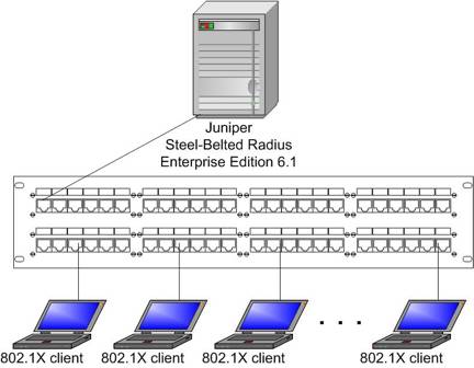
This table gives the addresses and VLANs in use:
|
Device |
VLAN ID |
IPv4 address |
|
Switch |
101 |
10.0.0.1 |
|
DHCP server/primary
domain controller |
101 |
10.0.11 |
|
Authentication server |
101 |
10.0.0.11 |
|
Clients |
101, (102) |
10.0.0.20-10.0.255.254 |
The authentication server for this project is Juniper
Steel-Belted Radius (SBR) Enterprise Edition Version 6.1 running on Windows
Advanced Server 2003 R2. We configure the authentication server and clients to
use PEAP and MS-CHAPv2 for logins.
The same Windows Advanced Server 2003 R2 machine acts as a
primary domain controller for the domain FREEDONIA and as a DHCP server.
The clients will use Windows Active Directory usernames and
passwords.
3.3.3
Procedure
- Using
802.1X login(s), determine which of the following procedures the switch
supports:
- One
user per port, successful 802.1X authentication, switch permits user
traffic onto predefined VLAN 101 (untagged)
- Multiple
users per port, successful 802.1X authentication, switch permits all
users traffic onto predefined VLAN 101 (untagged)
- Same
as (a), but switch dynamically assigns VLAN 101 (untagged) to port (port
is not a VLAN member to begin with)
- Same
as (a), but switch dynamically assigns an access control list (ACL)
covering user traffic on that port
- Same
as (a), authentication fails, user placed in guest/fallback VLAN
- Fallback
to MAC authentication for non-802.1X client, eg., a printer
3.3.4
Metrics
802.1X (and other) authentication methods supported
3.3.5
Reporting requirements
DUT configuration
DUT software
version
Radius server
configuration
Test results
3.4
Storm control
3.4.1
Objective
To determine the ability of the DUT to repel or block
various forms of flooding attacks
3.4.2
Test bed configuration
For L2 and L3 tests, the DUT should be configured as in the
L2 and L3 basic performance tests above, respectively. If anti-flooding
mechanisms are not enabled by default, they should be for this test.
These tests examine the ability of the DUT to block or repel
various types of flooding attacks. On the principle that “crackers don’t make
appointments,” we do not release the specific attacks to vendors before test
time. What we can say is that attack sources will be a combination of
commercial and/or open-source tools and may involve some or all of the
following traffic types:
L2: BPDU flooding, random MAC flooding, 802.1X auth request
flooding
L3 and above: ARP spoofing, DHCP spoofing, IP spoofing, SSH
redirection, SSL redirection
3.4.3
Procedure
- Configure
the switch in L2 mode. Offer various L2 attacks to multiple gigabit and/or
10 gigabit interfaces at rates exceeding at least 10 percent of line rate.
While offering attack traffic, determine the following:
- the
switch drops all attack packets
- the
switch drops all attack packets by default (i.e., no additional user
configuration is needed for this safeguard)
- the
command-line remains responsive (i.e., a user can log in and view the
running configuration)
- the
switch logs the attack attempt
- Repeat
previous step with switch configured in L3 mode, and L3 (and possibly
higher) attacks offered to DUT.
3.4.4
Metrics
Attacks blocked
Attacks forwarded
Storm controls supported
Storm controls supported by default
Responsiveness while under attack
Attack logging
3.4.5
Reporting requirements
DUT configuration
DUT software
version
Attack source(s)
configuration
Test results
3.5
Power consumption
3.5.1
Objectives
To determine the
power consumption of the DUT when idle
To determine the
power consumption of the DUT when fully loaded
3.5.2
Test bed configuration
This test uses
the following equipment:
·
Fluke 335
True-RMS clamp meter
·
WaveTek ELS2
AC line splitter
·
Spirent
TestCenter chassis
The DUT plugs
into the line splitter and the clamp meter measures power consumption through
the line splitter. The Spirent TestCenter chassis attaches to two 10G Ethernet
and 48 gigabit Ethernet interfaces of the DUT.
This test will
measure power consumption when idle and again when fully loaded. “Fully loaded”
in this context means maximum utilization of the DUT’s control and data planes.
Test traffic will
comprise 64-byte UDP/IP frames with at least one IP option set to force
“slow-path” processing by the DUT. The tester should verify that CPU
utilization rises when IP options are in use; if not, other mechanisms such as
management requests or flooding may be used, provided it has the effect of
maximizing CPU utilization.
3.5.3
Procedure
1. Using the clamp meter and leads, measure
AC voltage from the power outlet. We refer to this measurement as V.
2. Plug the DUT into the line splitter and
verify the system has booted up.
3. Place the clamp meter jaws around the
“10X” receptacle of the line splitter. The clamp meter will display AC amps
drawn by the DUT times 10. We refer to this figure as 10A.
4. Derive idle-DUT power consumption in watts
(W) using the formula W = V * (10A/10).
5. Using Spirent TestCenter, offer 64-byte
frames to all interfaces at the throughput rate as determined in the previous
test of L3 basic performance. The traffic orientation must be directional
between the 10G interfaces and fully meshed between all gigabit Ethernet
interfaces. Also, see comments about setting IP options in “Test Bed
Configuration” above.
6. Repeat steps 3-4 to determine maximum-load
power consumption.
7. For devices with multiple power supplies,
repeat all previous steps for each power supply. Add wattage from each power
supply to determine total system power consumption.
3.5.4
Metrics
Supplied power
(volts AC)
Idle power
consumption (watts)
Maximum-load
power consumption (watts)
3.5.5
Reporting requirements
DUT configuration
DUT software
version
Spirent
TestCenter configuration
Test results
3.6
L2 unicast performance
3.6.1
Objectives
To determine
throughput, delay, and sequencing of the DUT when forwarding unicast Ethernet
frames based on L2 forwarding criteria
3.6.2
Test bed configuration
This device under
test (DUT) is equipped with two 10-gigabit Ethernet interfaces and 48 gigabit
Ethernet interfaces. We attach Spirent TestCenter 1- and 10-Gbit/s Ethernet
test interfaces to the DUT. We assume the use of XFP SR optics for the 10G
interfaces unless otherwise specified, and 1000Base-T copper interfaces with
RJ-45 connectors for the gigabit interfaces.
We configure
Spirent TestCenter to offer two sets of streams: bidirectional traffic between
the 10G interfaces, and fully meshed traffic between the gigabit Ethernet
interfaces. RFC 2285 describes
traffic orientation and distribution. As described in the procedures section,
tests will measure gigabit and 10 gigabit performance separately and together.
Test traffic
offered to all ports will have 10 MAC addresses per port, and will use pseudorandom
MAC addresses as described in RFC
4814.
The DUT must be
configured so that entries in its bridging table will not age out during the
test.
The DUT must be
configured to disable spanning tree, routing protocols, multicast and any other
protocols that might put control-plane traffic on the wire during the test
duration. The goal of this test is to determine maximum data-plane performance,
and the existence of even one extra frame other than test traffic can lead to
frame loss.
3.6.3
Procedure
1. Perform a learning run to populate the
DUT’s bridging table.
2. Using a binary search algorithm, we offer
bidirectional streams of test traffic to 10G interfaces for 60 seconds to
determine the throughput rate, latency (using LILO method), and frames received
out of sequence (if any).
3. We repeat the previous step for each of
the following Ethernet frame lengths: 64, 256, and 1518 bytes.
4. We repeat steps 2-3 for gigabit
interfaces. In this case, we offer fully meshed traffic to all 48 gigabit
interfaces.
5. We repeat steps 2-4 with 10G and gigabit
traffic offered concurrently.
3.6.4
Metrics
Throughput (64,
256, and 1518 byte frames) (gigabit, 10G, and combined)
Average and
maximum latency (64, 256, and 1518 byte frames) (gigabit, 10G, and combined)
Out of sequence
frames
3.6.5
Reporting requirements
DUT configuration
DUT software
version
Spirent
TestCenter configuration
Test results
3.7 L3
unicast performance
3.7.1
Objectives
To determine
throughput, delay, and sequencing of the DUT when forwarding unicast IPv4
traffic
3.7.2
Test bed configuration
This device under
test (DUT) is equipped with two 10-gigabit Ethernet interfaces and 48 gigabit
Ethernet interfaces. We attach Spirent TestCenter 1- and 10-Gbit/s Ethernet
test interfaces to the DUT. We assume the use of XFP SR optics for the 10G
interfaces unless otherwise specified, and 1000Base-T copper interfaces with
RJ-45 connectors for the gigabit interfaces.
We configure
Spirent TestCenter to offer two sets of streams: bidirectional traffic between
the 10G interfaces, and fully meshed traffic between the gigabit Ethernet
interfaces. RFC 2285 describes
traffic orientation and distribution. As described in the procedures section,
tests will measure gigabit and 10 gigabit performance separately and together.
We use static
routing for this test. The following table lists the IPv4 addressing in use on
the DUT and test instrument:
|
Interface type |
Port IP address length/prefix length |
Interface type |
Port IP address length/prefix length |
Host(s) emulated |
|
GE |
10.1.0.1/16 |
GE |
10.1.0.2/16 |
10.1.0.3-10.1.0.12 |
|
GE |
10.2.0.1/16 |
GE |
10.2.0.2/16 |
10.2.0.3-10.2.0.12 |
|
GE |
10.3.0.1/16 |
GE |
10.3.0.2/16 |
10.3.0.3-10.3.0.12 |
|
GE |
.. |
GE |
.. |
.. |
|
GE |
10.48.0.1/16 |
GE |
10.48.0.2/16 |
10.48.0.3-10.48.0.12 |
|
10GE |
10.101.0.1/16 |
10GE |
10.101.0.2/16 |
10.101.0.3-10.101.0.12 |
|
10GE |
10.102.0.1/16 |
10GE |
10.102.0.2/16 |
10.102.0.3-10.102.0.12 |
The DUT must be
configured so that entries in its ARP and bridging tables will not age out
during the test duration. This can be done either by disabling aging or setting
it to a value larger than the test duration.
The DUT must be
configured to disable spanning tree, routing protocols, multicast and any other
protocols that might put control-plane traffic on the wire during the test
duration. The goal of this test is to determine maximum data-plane performance,
and the existence of even one extra frame other than test traffic can lead to
frame loss.
Test traffic will
use pseudorandom MAC addresses as described in RFC 4814.
3.7.3
Procedure
1. Perform a learning run to populate the
DUT’s bridging table.
2. Using a binary search algorithm, we offer
bidirectional streams of test traffic to 10G interfaces for 60 seconds to
determine the throughput rate, latency (using LILO method), and frames received
out of sequence (if any).
3. We repeat the previous step for each of
the following Ethernet frame lengths: 64, 256, and 1518 bytes.
4. We repeat steps 2-3 for gigabit
interfaces. In this case, we offer fully meshed traffic to all 48 gigabit
interfaces.
5. We repeat steps 2-4 with 10G and gigabit
traffic offered concurrently.
3.7.4
Metrics
Throughput (64,
256, and 1518 byte frames) (gigabit, 10G, and combined)
Average and
maximum latency (64, 256, and 1518 byte frames) (gigabit, 10G, and combined)
Out of sequence
frames
3.7.5
Reporting requirements
DUT configuration
DUT software
version
Spirent
TestCenter configuration
Test results
3.8
IGMP multicast group capacity
3.8.1
Objectives
To determine the maximum number of IGMP multicast groups the
DUT can support while maintaining the ability to forward multicast frames to
all multicast groups registered to the DUT (adapted from RFC 3918).
3.8.2
Test bed configuration
The DUT should be configured to support IGMPv3. Spirent
TestCenter should be configured to support IGMPv3 multicast transmitters and
receivers, with one receiver and one transmitter per multicast group. Multicast
group addresses will begin at 225.0.0.1.
The DUT and Spirent TestCenter must be configured in L2
mode, similar to the configured in the L2 unicast performance test, with two
exceptions: In this test, only 47 gigabit Ethernet interfaces join multicast
groups. Also, IGMPv3 should be enabled, including IGMP snooping. The DUT should
be configured with an IP address 10.101.0.1/16 to act as a source for IGMP
queries.
The test procedure will determine the DUT’s query interval.
To avoid the possibility that the test tool sends report (join) messages too
fast for the DUT to process, the test script will wait 2X the DUT’s IGMP query
interval. This will allow the DUT to go through the normal IGMP query/report
process, “filling out” any missing entries in its IGMP membership table.
The DUT must be
configured to disable spanning tree and unicast routing protocols.
A 10G interface on Spirent TestCenter will act as
transmitter for all multicast groups, and 47 gigabit interfaces on Spirent
TestCenter will act as receivers for all multicast groups. The 48th gigabit
interface of Spirent TestCenter will act as a monitor port; if the switch
forwards any multicast frames to that port, the test iteration is considered a
failure.
This test runs from a TCL script generated by Spirent
ScriptMaster. Since the DUT is in L2 mode, all hosts are in the same IP subnet.
The following table lists IP addresses used by the test script:
|
Port type |
Multicast role |
Emulated host address |
|
Gigabit Ethernet |
Receiver |
10.101.0.3/16 |
|
Gigabit Ethernet |
Receiver |
10.101.0.4/16 |
|
.. |
.. |
.. |
|
Gigabit Ethernet |
Receiver |
10.101.0.50/16 |
|
10G Ethernet |
Source |
10.101.0.51/16 |
3.8.3
Procedure
- Prior
to offering test traffic but after enabling IGMP, capture traffic from a
DUT receiver port for at least 5 minutes. Note the frequency of IGMP
queries, as it will be used in the next step.
- Each
of 47 receiver ports will join 100 multicast groups. After a delay of 2X
the DUT’s query interval, Spirent TestCenter will transmit 1,518-byte
multicast traffic to all receivers in all groups at an aggregate rate of
0.1 percent of 10G line rate for a duration of 60 seconds. If Spirent
TestCenter receives one or more frames per group, the iteration is said to
pass at the current capacity, per RFC 3918. If the 48th (monitor) port
receives multicast traffic and/or if one or more multicast groups on the
47 gigabit test ports fail to receive traffic, the iteration is said to
fail.
- The
test instrument will use a binary search algorithm to determine the
maximum number of groups supported. The test stops iterating when one or
more of the egress interfaces fails to forward traffic on one or more of
the configured multicast groups.
3.8.4
Metrics
Total number of multicast group addresses successfully
forwarded through the DUT
3.8.5
Reporting requirements
DUT configuration
DUT software
version
Spirent
TestCenter configuration
Test results
3.9
L2 multicast performance
3.9.1
Objectives
To determine the
throughput and average latency of the DUT when forwarding IPv4 multicast
traffic to hosts on a single VLAN/IP subnet (RFC 3918 aggregated multicast
throughput and multicast forwarding latency)
3.9.2
Test bed configuration
These tests use TCL scripts generated by Spirent
ScriptMaster 2.0.74. The scripts measure RFC 3918 aggregated multicast throughput and multicast forwarding latency.
The DUT should be configured to support IGMP. Spirent TestCenter
should be configured to support multicast transmitters (on the DUT’s first 10G
interface) and receivers (on 48 gigabit interfaces).
Each of 48 Spirent TestCenter gigabit interfaces should be
configured to join 500 multicast groups, each with 1 transmitter. All receivers
will join the same 500 groups. Multicast group addresses will begin at
225.0.1.0. The IGMPv3 report (join) messages will include a source filter to
include traffic from the transmitter at 10.101.0.51.
If the IGMP group capacity tests determine the DUT cannot
support 500 multicast groups, tests instead will be run at the capacity level
(with this setup detail noted along with test results).
The DUT and Spirent TestCenter must be configured with all
IP addresses in the same VLAN/IP subnet. The script for this test uses the same
IP addresses as those in the “IGMP group capacity” test.
The test procedure will determine the DUT’s query interval.
To avoid the possibility that the test tool sends report (join) messages too
fast for the DUT to process, the test script will wait 2X the DUT’s IGMP query
interval. This will allow the DUT to go through the normal IGMP query/report
process, “filling out” any missing entries in its IGMP membership table.
The DUT must be
configured to disable spanning tree and unicast routing protocols.
3.9.3
Procedure
- Prior
to offering test traffic but after enabling IGMP, capture traffic from a
DUT receiver port for at least 5 minutes. Note the frequency of IGMP
queries, as it will be used in the next step.
- Each
receiver port will join 500 multicast groups beginning at 225.0.1.0 using
IGMPv3 reports (joins). The report messages use an include filter for
traffic sourced from 10.101.0.51.
- After a delay of 2X the DUT’s query interval (determined in
step 1), perform a learning run to populate the DUT’s bridging table.
- Using a binary search algorithm, we offer test traffic to the
DUT’s first 10G port destined to all 500 multicast group addresses to
determine the throughput rateand frames received out of sequence (if any).
The test duration is 60 seconds.
- At the throughput rate, we again offer traffic to all 500
multicast groups to measure average and maximum latency.
- We repeat the previous two steps for each of the following
Ethernet frame lengths: 64, 256, and 1518 bytes.
3.9.4
Metrics
Multicast
throughput (64, 256, and 1518 byte frames)
Average and
maximum latency (64, 256, and 1518 byte frames)
Out of sequence
frames (pass/fail)
3.9.5
Reporting requirements
DUT configuration
DUT software
version
Spirent
TestCenter configuration
Test results
3.10 L3
multicast performance
3.10.1Objectives
To determine the
throughput and average latency of the DUT when forwarding IPv4 multicast
traffic to hosts on a multiple VLAN/IP subnets (RFC 3918 aggregated multicast throughput and multicast
forwarding latency)
3.10.2Test bed configuration
These tests use TCL scripts generated by Spirent
ScriptMaster 2.0.74. The scripts measure RFC 3918 aggregated multicast throughput and multicast forwarding latency.
The DUT should be configured to support IGMP. Spirent TestCenter
should be configured to support multicast transmitters (on the DUT’s first 10G
interface) and receivers (on 48 gigabit interfaces).
The physical topology of this test is similar to that in the
test for “L2 multicast performance.” However, this time each DUT port should be
configured to use a different IP subnet. The IP subnetting is identical to that
used in the “L3 unicast performance” tests.
Each of 48 Spirent TestCenter gigabit interfaces should be
configured to join 500 multicast groups, each with 1 transmitter. All receivers
will join the same 500 groups. Multicast group addresses will begin at
225.0.1.0. The IGMPv3 report (join) messages will include a source filter to
include traffic from the transmitter at 10.101.0.3.
If the IGMP group capacity tests determine the DUT cannot
support 500 multicast groups, tests instead will be run at the capacity level
(with this setup detail noted along with test results).
PIM-sparse mode should be enabled on the DUT. IP unicast
routing protocol(s) may be enabled as well, if necessary. PIM-SM with
source-specific multicast (SSM) may be enabled but this is not mandatory.
Definition of a PIM-SM rendezvous point (RP) is optional for
this test. If an RP is needed, it must be statically defined either to a loopback
interface address or to the first 10G interface (10.101.0.1/16), covering the
entire IPv4 multicast space (224.0.0.0/4). A PIM-SM boostrap router (BSR) does
not need to be configured for this test.
The test procedure will determine the DUT’s query interval.
To avoid the possibility that the test tool sends report (join) messages too
fast for the DUT to process, the test script will wait 2X the DUT’s IGMP query
interval. This will allow the DUT to go through the normal IGMP query/report
process, “filling out” any missing entries in its IGMP membership table.
The DUT must be
configured to disable spanning tree protocol and any other extraneous
control-plane traffic that might reduce throughput.
3.10.3Procedure
- Prior
to offering test traffic but after enabling IGMP, capture traffic from a
DUT receiver port for at least 5 minutes. Note the frequency of IGMP
queries, as it will be used in the next step.
- Each
receiver port will join 500 multicast groups beginning at 225.0.1.0 using
IGMPv3 reports (joins). The report messages use an include filter for
traffic sourced from 10.101.0.3.
- After a delay of 2X the DUT’s query interval (determined in
step 1), perform a learning run to populate the DUT’s bridging table.
- Using a binary search algorithm, we offer test traffic to the
DUT’s first 10G port destined to all 500 multicast group addresses to
determine the throughput rateand frames received out of sequence (if any).
The test duration is 60 seconds.
- At the throughput rate, we again offer traffic to all 500
multicast groups to measure average and maximum latency.
- We repeat the previous two steps for each of the following
Ethernet frame lengths: 64, 256, and 1518 bytes.
3.10.4Metrics
Multicast
throughput (64, 256, and 1518 byte frames)
Average and
maximum latency (64, 256, and 1518 byte frames)
Out of sequence
frames (pass/fail)
3.10.5Reporting requirements
DUT configuration
DUT software
version
Spirent
TestCenter configuration
Test results
4 Change log
Version 2008012101
21 January 2008
Title matter: Changed publication date from “December 2007”
to “March 2008”
Section 3.8: Modified multicast group capacity test
procedure to add monitor port. This addresses a logic flaw in RFC 3918,
detailed here:
http://www1.ietf.org/mail-archive/web/bmwg/current/msg01657.html
Version 2007110401
4 November 2007
Title matter: Changed publication date from “late fall” to
“December 2007”
Executive summary: Divided multicast performance tests into
L2 and L3 events; retitled “basic” L2 and L3 tests to unicast L2 and L3 tests;
deleted QoS enforcement test
Section 2.1: Changed device requirement to one switch
Section 2.2.2: Corrected addressing for Steel-Belted Radius
(now runs on same machine as Windows Server PDC)
Section 3.3.2: Corrected addressing for Steel-Belted Radius
(now runs on same machine as Windows Server PDC)
Sections 3.6 and 3.7: Clarified title and objective to
indicate use of unicast traffic
Section 3.7.2: Corrected host addressing table for 10G
interfaces (10 hosts/port, not 1024)
Deleted former section 3.8 on QoS enforcement
Section 3.8 (now IGMP group capacity): Changed from DUT L3
to L2 mode; increased receiver port count from two to 48; added addressing used
by TCL scripts; increased group report delay from 10 seconds to 2X query
interval; changed offered load for test traffic from 100 fps to 0.1 percent 10G
line rate; added specification that test traffic duration is 60 seconds.
Section 3.9 (now L2 multicast performance)
Section 3.9.1: Dropped flooding from test objective
Sections 3.9.2-3: Tests now use 48 receiver ports (was 10)
Section 3.10 (now L2 multicast performance)
Section 3.10.1: Dropped flooding from test objective
Sections 3.10.2-3: Tests now use 48 receiver ports (was 10)
Version 2007092401
24 September 2007
Initial public release